Retaining Wall Design Example With Surcharge Load

Cantilever Retaining Wall Design Example Using Asdip Retain Software

Cantilever Retaining Wall Uniform Surcharge Loading Factors Of Safety For Overturning And Sliding Youtube
Surcharge Point Loads Spreadsheet

Loads And Forces Acting On Retaining Wall And Their Calculations Pdf
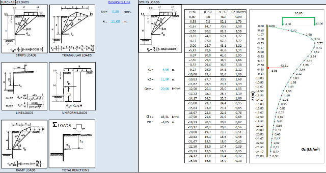
Surcharge Loads Types Spreadsheet

Retaining Walls Surcharge Load Calculation

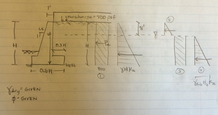
Based on our example in figure a 1 we have the forces due to soil pressure due to water and surcharge load to consider.
Retaining wall design example with surcharge load.

Combination Retaining Wall And Foundation Wall Structural Engineering General Discussion Eng Tips

Lateral Pressure On Retaining Wall Due To A Line Load Surcharge Download Scientific Diagram

Guidance For The Design Of A Reinforced Concrete Retaining Wall Structural Engineering General Discussion Eng Tips
Https Www Arema Org Files Library 2014 Conference Proceedings Retaining Wall Design For The Railroad Infrastructure Pdf
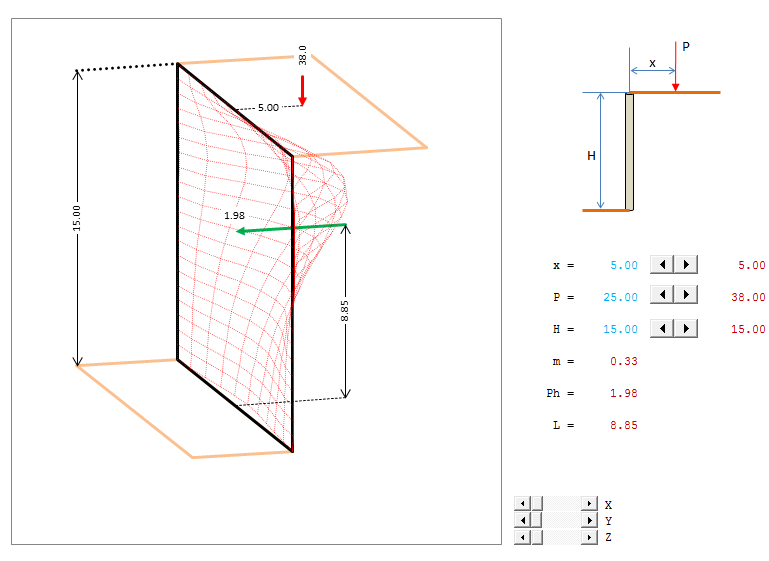
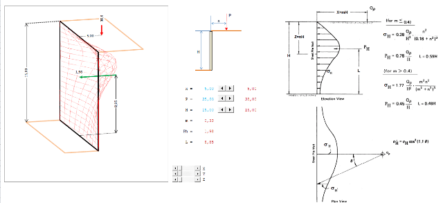
Surcharge Loads Point Load

Design Of Structures Design Of Retaining Wall With Surcharge Load Inclined At Some Angle Mechanics Continuum Mechanics

Design Of Reinforced Concrete Cantilever Retaining Wall Using Grey Wolf Optimization Algorithm Sciencedirect
How To Analyse Retaining Walls For Trapezoidal Load Structville
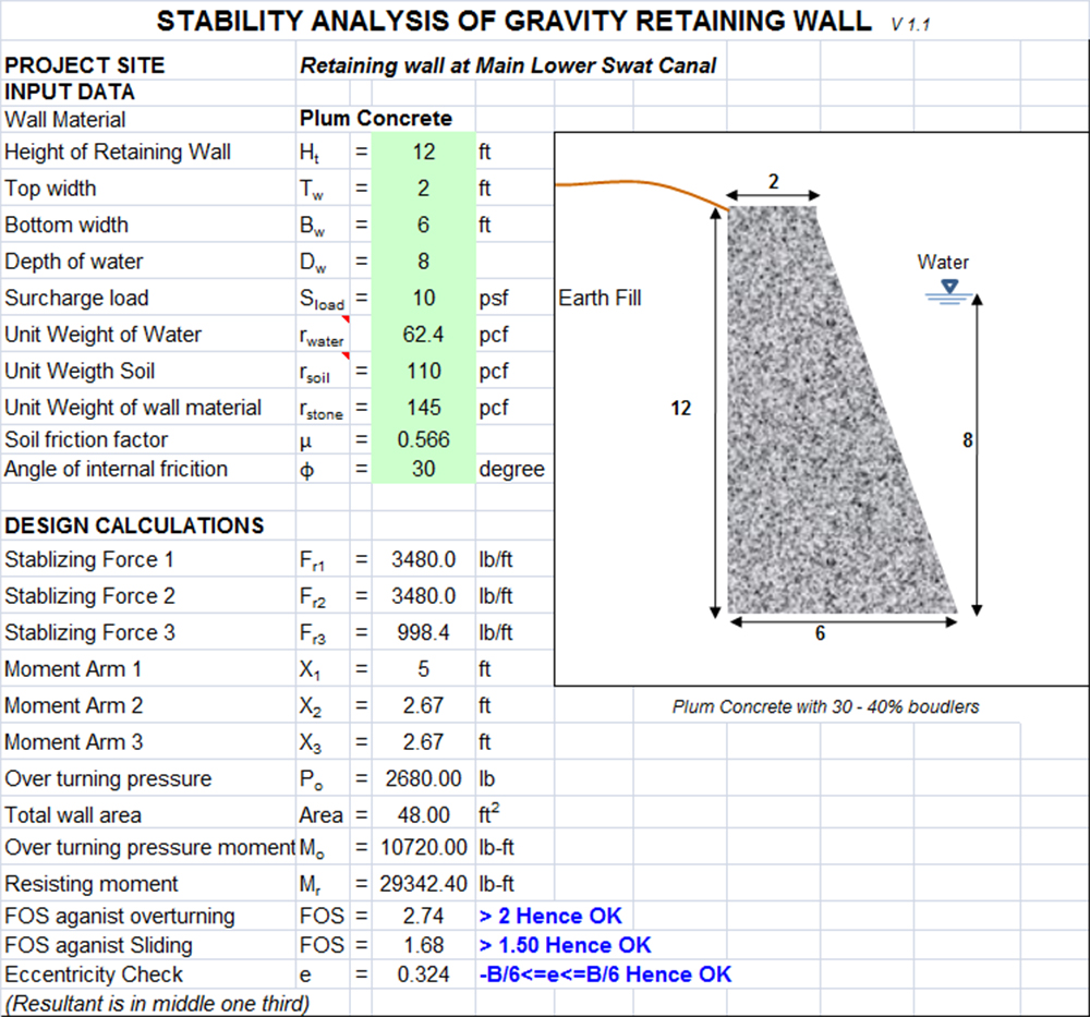
Design Of Gravity Retaining Walls In Excel Sloped And Stepped
Solved Design A Rcc Cantilever Retaining Wall To Remain A Chegg Com

Additional Earth Pressure Of Retaining Wall Caused By Vehicle Load

Retaining Wall Design Will Contain Any Or All Of Loads And Forces Which Are Briefly Described In The Following Sectio Retaining Wall Design Retaining Wall Wall

Overview Of General Retaining Wall Design On The Se Exam
Builder S Engineer Design Considerations For A Mechanically Stabilized Earth Wall

A Counterfort Retaining Wall With C Backfill And Surcharge Load Q Download Scientific Diagram
How To Design A Cantilever Soldier Pile Embedded Retaining Wall Soilstructure Software
Point Load Surcharges Applied At A Setback Distance Greater Than 1h Soilstructure Software

Cantilever Retaining Wall Bearing Pressure Calculation Asdip Software
Https Encrypted Tbn0 Gstatic Com Images Q Tbn 3aand9gcrzgt6wny8efawi73u3oindaxjegjtpepbpvus9wqiuw1vaf6lr Usqp Cau

Earth Pressure 14 2 2012
Https Www Mdpi Com 2076 3417 10 9 3232 Pdf
Https Www Scdot Org Business Pdf Geotech Chapter 2018 20earth 20retaining 20structures Pdf

Basement Wall Design Example Using Asdip Retain Structural Software
Https Www Codot Gov Library Bridge Bridge Manuals Design Manual Bdm Section 11 2020 02 Pdf
Source : pinterest.com
